Combine direct rainfall and sewerage inflow
3Di can be used to model any sanitary, storm and combined sewerage system, with water entering the model using the 0D inflow in combination with 2D rainfall. Combining Rainfall on 0D node (inflow) with and 2D rain can be useful in several cases, for example:
Detailed urban water management models that use 0D inflow for the flow of water from roofs to the sewerage and 2D surface for rainfall and discharge over roads
Large open water systems in which a small area is modeled in detail while upstream catchments are lumped in 0D inflow.
Schematisation
Adding 0D inflow
Follow the steps explained in Use rainfall-runoff (0D inflow) in 1D models
Adding 2D rainfall
Areas included in the 0D inflow should be excluded from the 2D rainfall. There are two ways to exclude rain from falling in the 2D domain:
Adding a Interception raster
Removing the (impervious) surfaces from the 2D rasters
Interception
Interception specifies the amount of rain which can be intercepted. This parameter can also be used to intercept only precipitation where 0D-inflow surfaces are defined. To generate a interception raster you could follow these steps:
Create a raster with only zero-values
Define at the locations of the surfaces an interception value that exceeds the total rainfall event. For example, if the total rainfall is 70 mm, an interception of >70 mm should be specified at the location of the surfaces.
The advantage of using interception is that the other rasters are not affected. Therefore it remains possible to have flow through (or below if using groundwater) the surfaces. A disadvantage is that the model becomes larger and might become too large for grid generation.
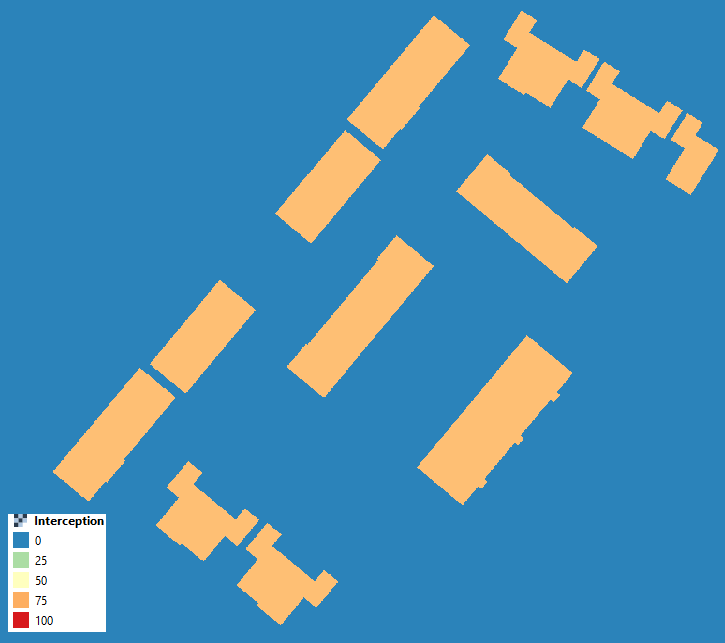
Fig. 4 An example of a interception raster
Removing the (impervious) surfaces from the 2D rasters
2D rain falls only where the DEM is defined. Therefore, by removing the (impervious) surfaces from the DEM (turning them into nodata) the precipitation is removed from the 2D domain. As all 2D rasters have to overlap precisely, one should remove the surfaces from the DEM and all other rasters present (i.e. infiltration, friction). The advantage of this method is that there is no additional raster required. A disadvantage might be that flow through (larger) surfaces will be obstructed.
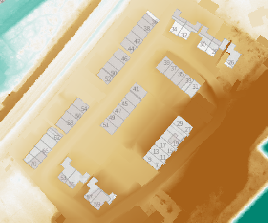
Fig. 5 Hybrid DEM with removed surfaces to limit 2D rainfall.
Simulation
Following the outlined steps, a 3Di model can be created based on the schematization. Rainfall occurring on either the Surface or Impervious surface will contribute to the volume of the designated calculation node, functioning as lateral discharge. Meanwhile, the remaining surfaces will undergo standard 2D Surface flow processes.